- 您现在的位置:买卖IC网 > Sheet目录1223 > KIT33887PNBEVB (Freescale Semiconductor)KIT EVAL 33887 5A H-BRIDGE PQFN
�� �
�
�ELECTRICAL� CHARACTERISTICS�
�DYNAMIC� ELECTRICAL� CHARACTERISTICS�
�DYNAMIC� ELECTRICAL� CHARACTERISTICS�
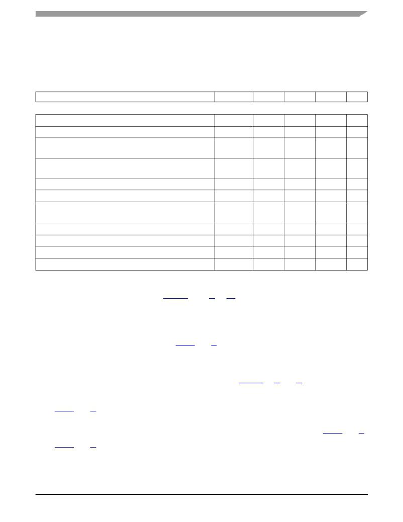
�Table� 5.� DYNAMIC� ELECTRICAL� CHARACTERISTICS�
�Characteristics� noted� under� conditions� 5.0� V� ≤� V+� ≤� 28� V� and� -40� °� C� ≤� T� A� ≤� 125� °� C� unless� otherwise� noted.� Typical� values�
�noted� reflect� the� approximate� parameter� mean� at� T� A� =� 25� °� C� under� nominal� conditions� unless� otherwise� noted.�
�Characteristic�
�Symbol�
�Min�
�Typ�
�Max�
�Unit�
�TIMING� CHARACTERISTICS�
�PWM� Frequency� (24)�
�f� PWM�
�–�
�10�
�–�
�kHz�
�Maximum� Switching� Frequency� During� Active� Current� Limiting�
�(25)�
�f� MAX�
�–�
�–�
�20�
�kHz�
�Output� ON� Delay� (26)�
�t� D� (ON)�
�μ� s�
�V+� =� 14� V�
�Output� OFF� Delay� (26)�
�V+� =� 14� V�
�t� D� (OFF)�
�–�
�–�
�–�
�–�
�18�
�18�
�μ� s�
�,�
�I� LIM� Output� Constant-OFF� Time� for� Low-Side� MOSFETs�
�I� LIM� Blanking� Time� for� Low-Side� MOSFETs� (29)� ,� (28)�
��t� A�
�t� B�
�15�
�12�
�20.5�
�16.5�
�26�
�21�
�μ� s�
�μ� s�
�Output� Rise� and� Fall� Time� (30)�
�t� F� ,� t� R�
�μ� s�
�V+� =� 14� V,� I� OUT� =� 3.0� A�
�2.0�
�5.0�
�8.0�
�Disable� Delay� Time� (31)�
�t� D� (DISABLE)�
�–�
�–�
�8.0�
�μ� s�
�Power-ON� Delay� Time�
�(32)�
�t� POD�
�–�
�1.0�
�5.0�
�ms�
�Wake-Up� Delay� Time� (32)�
�t� WUD�
�–�
�1.0�
�5.0�
�ms�
�Output� MOSFET� Body� Diode� Reverse� Recovery� Time�
�(33)�
�t� RR�
�100�
�–�
�–�
�ns�
�Notes�
�24� The� outputs� can� be� PWM-controlled� from� an� external� source.� This� is� typically� done� by� holding� one� input� high� while� applying� a� PWM�
�pulse� train� to� the� other� input.� The� maximum� PWM� frequency� obtainable� is� a� compromise� between� switching� losses� and� switching�
�frequency.� See� Typical� Switching� Waveforms,� Figures 12� through� 19� ,� pp.� 14–� 17.�
�25� The� Maximum� Switching� Frequency� during� active� current� limiting� is� internally� implemented.� The� internal� current� limit� circuitry� produces�
�a� constant-OFF-time� pulse-width� modulation� of� the� output� current.� The� output� load’s� inductance,� capacitance,� and� resistance�
�characteristics� affect� the� total� switching� period� (OFF-time� +� ON-time)� and� thus� the� PWM� frequency� during� current� limit.�
�26� Output� Delay� is� the� time� duration� from� the� midpoint� of� the� IN1� or� IN2� input� signal� to� the� 10%� or� 90%� point� (dependent� on� the� transition�
�direction)� of� the� OUT1� or� OUT2� signal.� If� the� output� is� transitioning� HIGH-to-LOW,� the� delay� is� from� the� midpoint� of� the� input� signal� to�
�the� 90%� point� of� the� output� response� signal.� If� the� output� is� transitioning� LOW-to-HIGH,� the� delay� is� from� the� midpoint� of� the� input� signal�
��27� I� LIM� Output� Constant-OFF� Time� is� the� time� during� which� the� internal� constant-OFF� time� PWM� current� regulation� circuit� has� tri-stated�
�the� output� bridge.�
�28� Load� currents� ramping� up� to� the� current� regulation� threshold� become� limited� at� the� I� LIM� value.� The� short� circuit� currents� possess� a� di/dt�
�that� ramps� up� to� the� I� SCH� or� I� SCL� threshold� during� the� I� LIM� blanking� time,� registering� as� a� short� circuit� event� detection� and� causing� the�
�shutdown� circuitry� to� force� the� output� into� an� immediate� tri-state� latch-OFF.� See� Figures 10� and� 11� ,� page� 13� .� Operation� in� Current� Limit�
�mode� may� cause� junction� temperatures� to� rise.� Junction� temperatures� above� ~160� °� C� will� cause� the� output� current� limit� threshold� to�
�progressively� “fold� back”,� or� decrease� with� temperature,� until� ~175� °� C� is� reached,� after� which� the� T� LIM� thermal� latch-OFF� will� occur.�
�Permissible� operation� within� this� fold-back� region� is� limited� to� nonrepetitive� transient� events� of� duration� not� to� exceed� 30� seconds.� See�
��29� I� LIM� Blanking� Time� is� the� time� during� which� the� current� regulation� threshold� is� ignored� so� that� the� short-circuit� detection� threshold�
�comparators� may� have� time� to� act.�
�30� Rise� Time� is� from� the� 10%� to� the� 90%� level� and� Fall� Time� is� from� the� 90%� to� the� 10%� level� of� the� output� signal.� See� Figure 8� ,� page� 12� .�
�31� Disable� Delay� Time� is� the� time� duration� from� the� midpoint� of� the� D� (disable)� input� signal� to� 10%� of� the� output� tri-state� response.� See�
��32� Parameter� has� been� characterized� but� not� production� tested.�
�33� Parameter� is� guaranteed� by� design� but� not� production� tested.�
�33887�
�Analog� Integrated� Circuit� Device� Data�
�Freescale� Semiconductor�
�11�
�发布紧急采购,3分钟左右您将得到回复。
相关PDF资料
KIT33905D5EKEVBE
KIT EVALUATION FOR MC33905
KIT33912EVME
KIT EVALUATION FOR MC33912
KIT33932VWEVBE
KIT EVALUATION FOR MC33932
KIT33982CEVBE
KIT EVAL 33982 HIGH SIDE SWITCH
KIT33984CEVBE
KIT EVAL 33984 HIGH SIDE SWITCH
KIT33988CEVBE
KIT EVAL 33988 HIGH SIDE SWITCH
KIT33996EKEVB
KIT EVAL 33996 16OUTPUT SW W/SPI
KIT34673EPEVBE
KIT EVALUATION FOR MC34673
相关代理商/技术参数
KIT33903BD3EVBE
功能描述:界面开发工具 3V DUAL LIN EVB KIT RoHS:否 制造商:Bourns 产品:Evaluation Boards 类型:RS-485 工具用于评估:ADM3485E 接口类型:RS-485 工作电源电压:3.3 V
KIT33903BD5EVBE
功能描述:界面开发工具 5V DUAL LIN EVB KIT
RoHS:否 制造商:Bourns 产品:Evaluation Boards 类型:RS-485 工具用于评估:ADM3485E 接口类型:RS-485 工作电源电压:3.3 V
KIT33905BD3EVBE
功能描述:界面开发工具 3V SNGL LIN EVB KIT RoHS:否 制造商:Bourns 产品:Evaluation Boards 类型:RS-485 工具用于评估:ADM3485E 接口类型:RS-485 工作电源电压:3.3 V
KIT33905D5EKEVBE
功能描述:界面开发工具 SBC GEN2 WITH HS CAN AND RoHS:否 制造商:Bourns 产品:Evaluation Boards 类型:RS-485 工具用于评估:ADM3485E 接口类型:RS-485 工作电源电压:3.3 V
KIT33905D5EKEVBE
制造商:Freescale Semiconductor 功能描述:Gen2 System Basis IC w/ CAN and LIN Inte
KIT33912EVME
功能描述:界面开发工具 For MC33912 RS-232 SPI RoHS:否 制造商:Bourns 产品:Evaluation Boards 类型:RS-485 工具用于评估:ADM3485E 接口类型:RS-485 工作电源电压:3.3 V
KIT33912G5DGEVME
功能描述:电源管理IC开发工具 33912G5 LIN SBC KIT RoHS:否 制造商:Maxim Integrated 产品:Evaluation Kits 类型:Battery Management 工具用于评估:MAX17710GB 输入电压: 输出电压:1.8 V
KIT33926PNBEVBE
功能描述:电源管理IC开发工具 5.2 A H-BRIDGE W/LOAD RoHS:否 制造商:Maxim Integrated 产品:Evaluation Kits 类型:Battery Management 工具用于评估:MAX17710GB 输入电压: 输出电压:1.8 V